Smart-ish Thermostat
Intro
If you haven't yet, go read part 1 first.
Problem/Inspiration
The EVSE needs to communicate with the central air system, but we still have those old mercury thermostats. No smart thermostat on the market can communicate with my custom protocol...so I guess I have to make a custom thermostat as well. My thermostat is smart, but in a different way.
The Process
The plan was simple:
1. Build and program a simple digital thermostat with an Arduino (temp too high, turn on; temp too low, turn off).
2. Add a way for it to communicate with the EVSE.
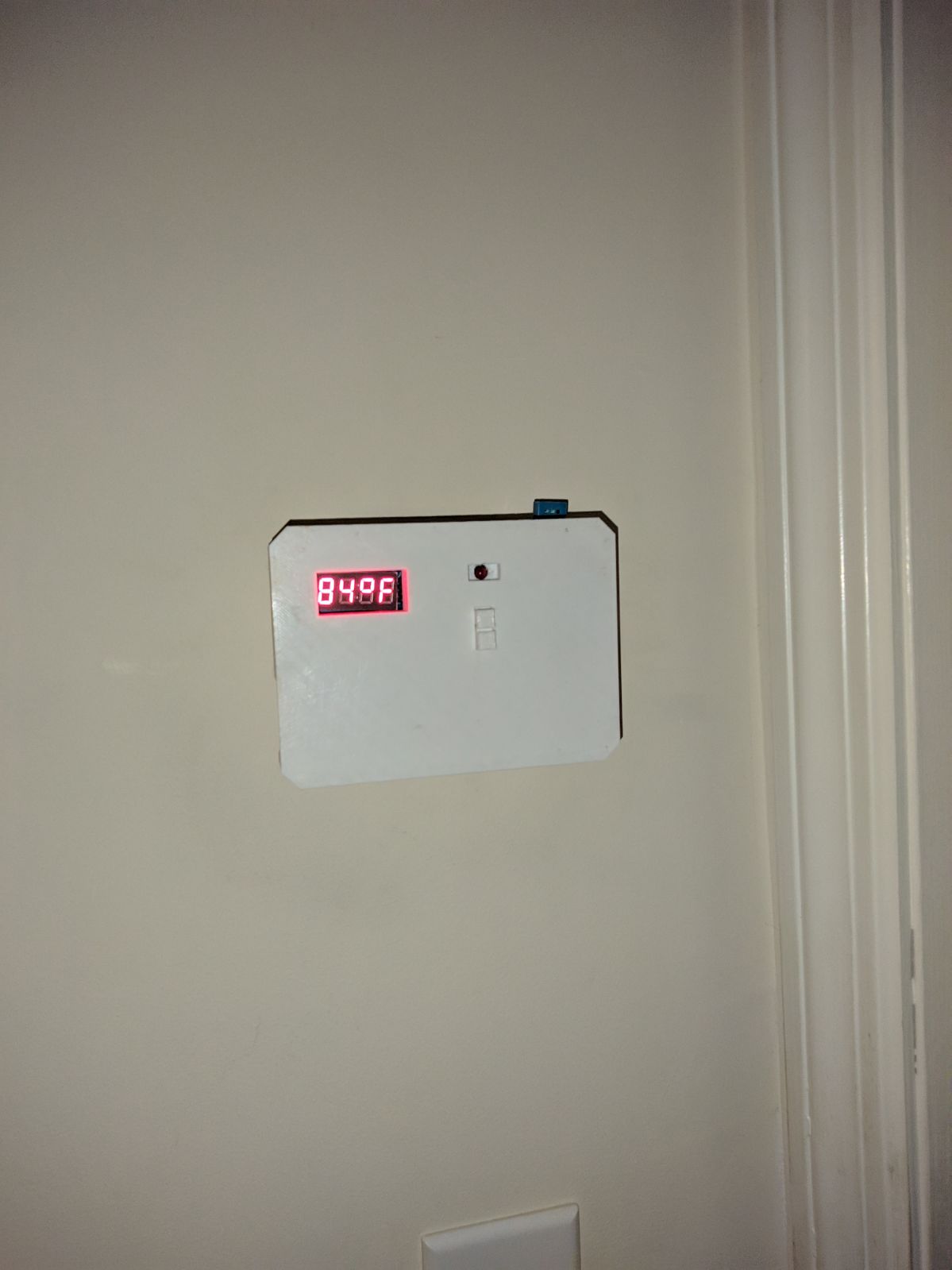
3. Design and 3D print a case for it.
4. Figure out a way to power the whole thing.
5. Mount it.
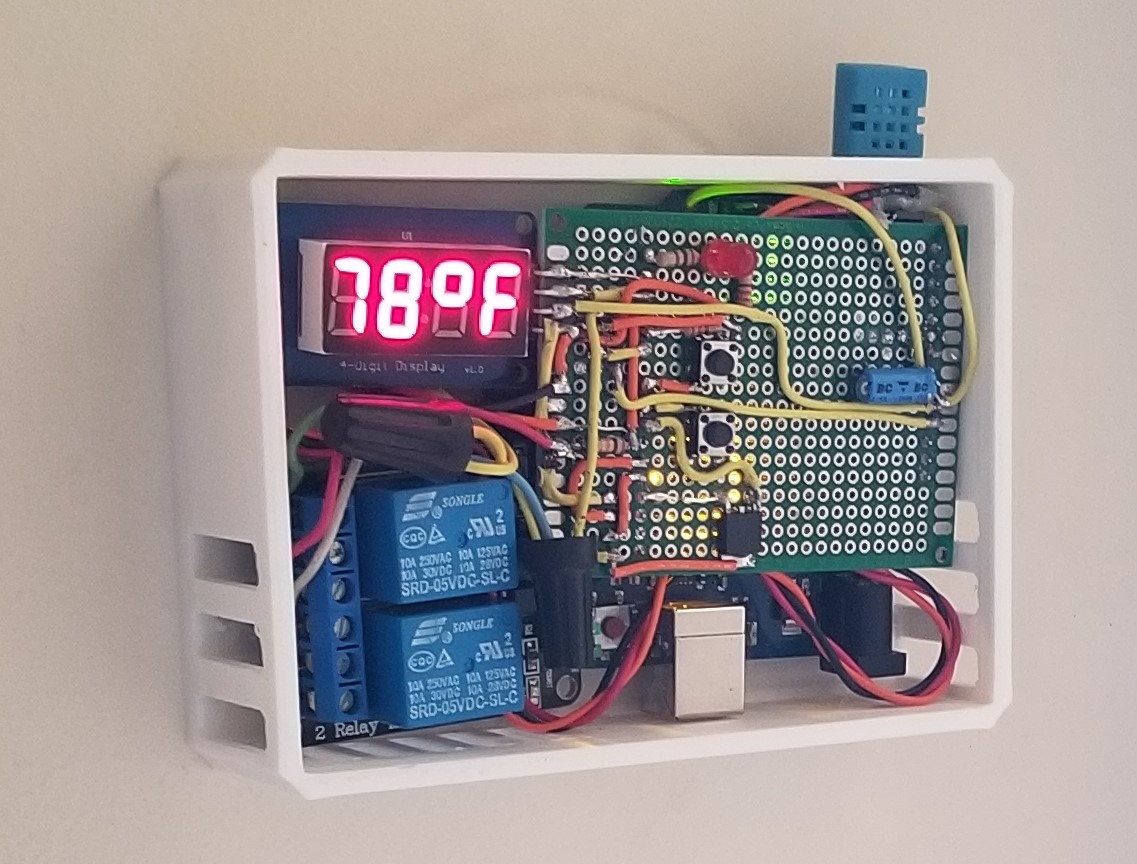
Nothing extraordinary came up during the actual build and programming of the thermostat-- a simple hysteresis program was implemented and for the sake of convenience, I decided to only use parts I already had in my parts bin. The thermostat circuit was up and running in half an hour. Total cost: $0.
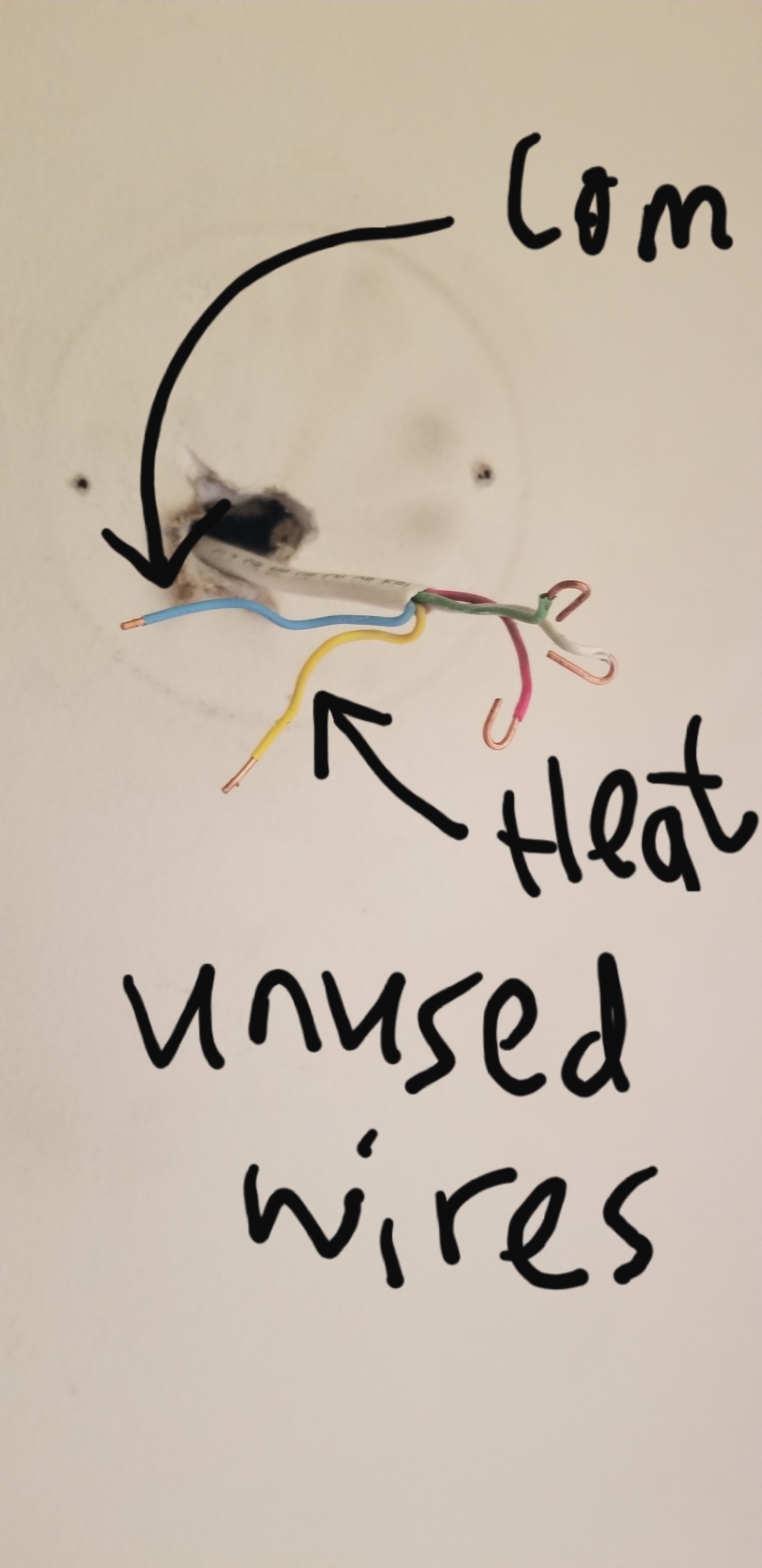
Unexpectedly, I got stuck on step 4. I didn't want to run a power cord from the outlet to the thermostat, cause that would look unprofessional, so I needed to find a way to power the thermostat through the wall. Unfortunately, the old thermostats were those bi-metal strip mercury kinds that didn't need a power source, so my house was not equipped with a working common wire. But even if there was one, I would still need to find a good way to convert that 24VAC to 5VDC to run the Arduino.
My original plan was to rectify that 24VAC (RMS voltage, so recified voltage would be ~34V) and step it down to 5V using a buck converter.
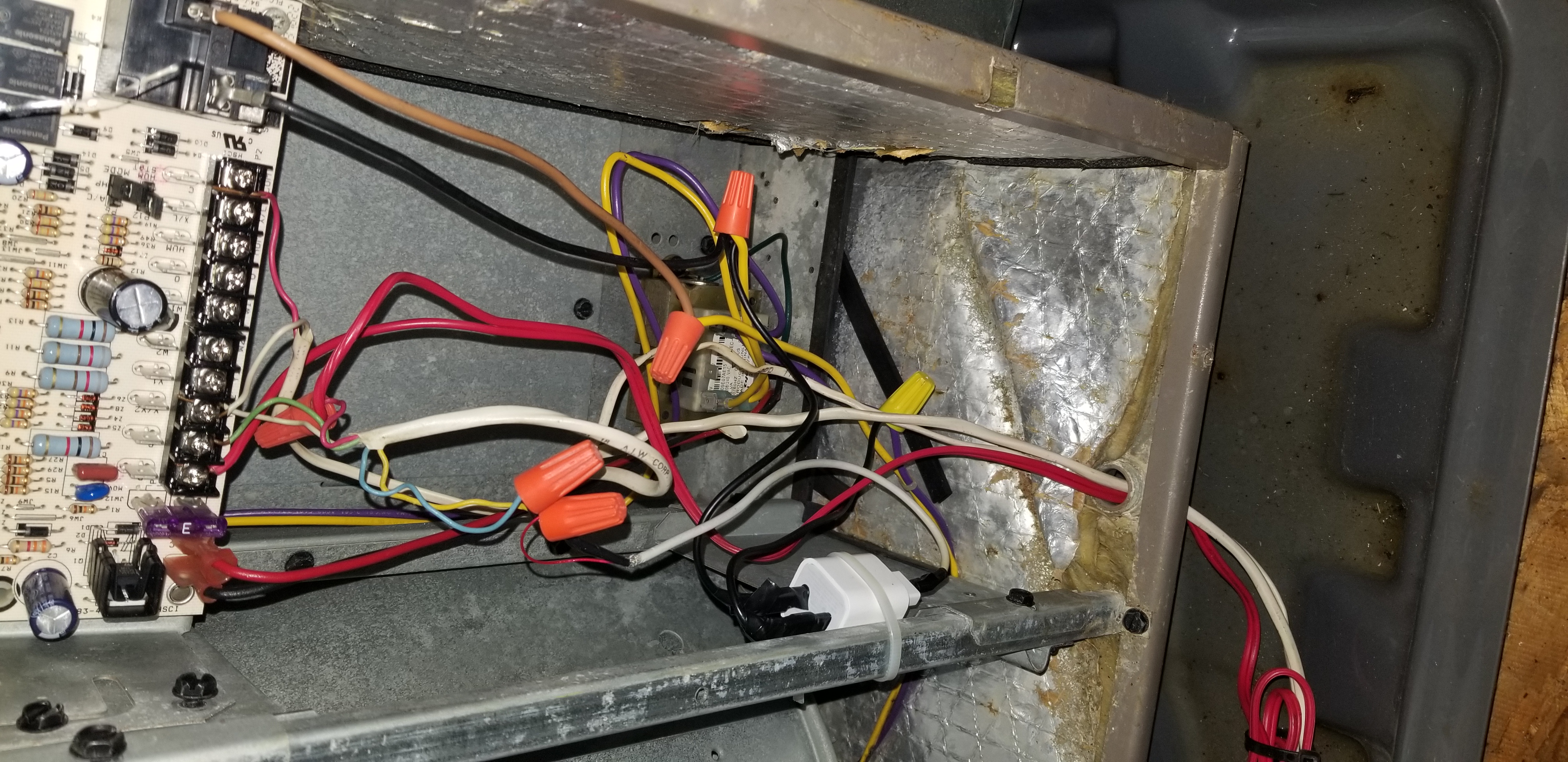
Fortunately, the common wire was there, but it wasn't hooked up (not a big issue, I can just climb into the attic and hook it up).
Unfortunately, I didn't have any buck converters laying around, and I couldn't wait a week for the parts to arrive. So I had to get creative.
My next idea was to rectify the 24VAC and feed it through a 12V regulator, which would get fed in to the Arduino's onboard 5V regulator. It would be extremely inefficient and things would get a bit warm, but I was under a time crunch. However, the efficiency nerd in me decided to do a quick test with a power supply to see how bad it would be.
Oh boy it was bad.
The microcontroller with both relays and ESP-01S on drew a total of around 300mA, which meant that at full power, that 12V regulator had to dissipate over 6.5W of power.
In other words, I could fry an egg on my thermostat.
Long story short, I played around with other crazy ideas until I blew the fuse in the blower fan controller. When I went to change the fuse, I realized that I could access 240VAC from the fan controller. Eureka! I had a few old phone charger bricks laying around that I can power using the 240VAC and get 5V directly! I delivered the 5V to the thermostat using the unused common and heating wires and called it done.
Remarks
Well, I certainly underestimated the difficulty of this sub-project. But in the end, the whole system works really well. When the AC wants to turn on, the thermostat will notify the EVSE to stop charging. If the message fails to send, it will try 5 more times before assume that the EVSE is off and proceed to turn on the AC system. Otherwise if the message was sent successfully, the thermostat will wait until the EVSE confirms that it has stopped charging before the thermostat turns on the AC.
If you haven't yet, go read part 1 first.
Problem/Inspiration
The EVSE needs to communicate with the central air system, but we still have those old mercury thermostats. No smart thermostat on the market can communicate with my custom protocol...so I guess I have to make a custom thermostat as well. My thermostat is smart, but in a different way.
The Process
The plan was simple:
1. Build and program a simple digital thermostat with an Arduino (temp too high, turn on; temp too low, turn off).
2. Add a way for it to communicate with the EVSE.
3. Design and 3D print a case for it.
4. Figure out a way to power the whole thing.
5. Mount it.
Nothing extraordinary came up during the actual build and programming of the thermostat-- a simple hysteresis program was implemented and for the sake of convenience, I decided to only use parts I already had in my parts bin. The thermostat circuit was up and running in half an hour. Total cost: $0.
Unexpectedly, I got stuck on step 4. I didn't want to run a power cord from the outlet to the thermostat, cause that would look unprofessional, so I needed to find a way to power the thermostat through the wall. Unfortunately, the old thermostats were those bi-metal strip mercury kinds that didn't need a power source, so my house was not equipped with a working common wire. But even if there was one, I would still need to find a good way to convert that 24VAC to 5VDC to run the Arduino.
My original plan was to rectify that 24VAC (RMS voltage, so recified voltage would be ~34V) and step it down to 5V using a buck converter.
Fortunately, the common wire was there, but it wasn't hooked up (not a big issue, I can just climb into the attic and hook it up).
Unfortunately, I didn't have any buck converters laying around, and I couldn't wait a week for the parts to arrive. So I had to get creative.
My next idea was to rectify the 24VAC and feed it through a 12V regulator, which would get fed in to the Arduino's onboard 5V regulator. It would be extremely inefficient and things would get a bit warm, but I was under a time crunch. However, the efficiency nerd in me decided to do a quick test with a power supply to see how bad it would be.
Oh boy it was bad.
The microcontroller with both relays and ESP-01S on drew a total of around 300mA, which meant that at full power, that 12V regulator had to dissipate over 6.5W of power.
In other words, I could fry an egg on my thermostat.
Long story short, I played around with other crazy ideas until I blew the fuse in the blower fan controller. When I went to change the fuse, I realized that I could access 240VAC from the fan controller. Eureka! I had a few old phone charger bricks laying around that I can power using the 240VAC and get 5V directly! I delivered the 5V to the thermostat using the unused common and heating wires and called it done.
Remarks
Well, I certainly underestimated the difficulty of this sub-project. But in the end, the whole system works really well. When the AC wants to turn on, the thermostat will notify the EVSE to stop charging. If the message fails to send, it will try 5 more times before assume that the EVSE is off and proceed to turn on the AC system. Otherwise if the message was sent successfully, the thermostat will wait until the EVSE confirms that it has stopped charging before the thermostat turns on the AC.